![]()
In this guide, the CIMON PLC-S/Micro-S CPU will be used to demonstrate Modbus Master configuration. The standalone PLC-S/Micro-S are capable of being a Modbus RTU Master/Slave and Modbus TCP Slave. However, a dedicated Ethernet module (i.e., CM3-SP01EET) is required to allow the CIMON PLC-S to become a Modbus TCP Master. The Micro-S is not capable of expanding and, as such, cannot ever be a Modbus TCP Master.
Registering a Modbus RTU/TCP Master Program
Click File > New Program > MODBUS/RTU Master or MODBUS/TCP Master within Communication Configuration > click OK.
- Slot – This field represents the card in the chassis responsible for the Modbus communication. Leave this field 0 for the CPU. Otherwise, choose the correct slot number if you are using a dedicated Ethernet/serial module.
- CH – Ch1 represents RS-232 and Ch2 represents RS-485 communication. Project Tree > Parameter > PLC Parameter > Channel 1/2 for configuration.
- New – Used to add an IP address for the target slave device. Project Tree > Parameter > PLC Parameter > Ethernet for configuration of CPU’s IP address.
- Result – The communication feedback for the protocol. Anything other than a 0 in this register means the communication is not stable.
- Add – Located at the bottom left-hand side, and is used to begin configuring a communication block.

In the sample screenshot above, the PLC-S/Micro-S CPU will be the Modbus RTU Master, denoted by Slot 0, communicating through RS-232 (Ch1) with a communication result in L0000. The Block No 0 is targeting Modbus Slave ID 3 with a 01 function code, reading a total of 1 address, in which 000001 is being stored to data register M0000. This communication will happen automatically.
Communication Block Configuration
- Block No – The program’s frame ID. Relevant for the SEND instruction.
- Station/Station No. – The Modbus Slave ID of the target device.
- Function – Codes 01, 02, 03, 04, 05, 06, and 16 are supported.
- Start Address – Do not put the full address in this field. As shown in the left image, Start Address 1 means 00001 since 01 Read Coil Status (0x) is selected in the Function field. Users can swap between HEX and DEC depending on their preference. Note: If HEX is showing, then the user is in decimal mode, and if DEC is showing, the user is then in hexadecimal mode.
- Data Type – Used when two devices are not cooperating with the data exchange. Typically, if modifications are needed at all, users only need to change INT16 (High-order byte first) to INT16 (Low-order byte first). Please consider that if you are transmitting floats or double-words that you only need to account for the offset (i.e., double-word in 40002 means 40002 + 40003) of Modbus addresses and can ignore the Float/INT32 options in this field.
- Data Count/Size – The number of registers being transmitted.
- Device – The PLC-S/Micro-S data register being read/written to/from.
- Do not transmit automatically – Check this box to control the rate of transfer. The SEND instruction is used in case this option is checked.
SEND Instruction for Controlling Data Transfer Rate
The SEND instruction is used to send frame data from a master station to slave stations, and it is executed by a pulse.
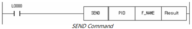
- PID – Program ID Number

- F_NAME – Frame number with communication type. Please see below for the proper structure. The format is of the form HXXYY.
-
- XX – Communication Type. 00 for RS232-C, 01 for RS485, and 0x for Ethernet depending on which data server you are communicating with (i.e., your first Ethernet data server would be 00, and second Ethernet data server would be 01, etc.)
- YY – Frame number (AKA Block No) within the program.
-


- Result – The feedback of the instruction being executed.
Example of Application
![]()