Modbus RTU/TCP Slave Configuration in CICON

In this guide, the CIMON PLC-S/Micro-S CPU will be used to demonstrate Modbus Slave configuration. The standalone PLC-S/Micro-S is a Modbus RTU/TCP Slave natively.
Registering the PLC-S/Micro-S as a Modbus RTU/TCP Slave
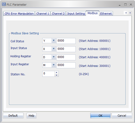
In the Project Window (Project Tree), expand the Parameter branch and double left-click PLC Parameter. Click the right arrow until you see Channel 1, Channel 2, Modbus, and Ethernet. Channel 1 and Channel 2 are used for configuring RS-232 and RS-485, respectively. The Modbus tab is for configuring your slave settings. The Ethernet tab is for configuring your CPU’s IP address.

Modbus Slave Setting Tab
- Natively, the PLC-S/Micro-S is a Modbus slave, and the Ethernet/serial parameters only need to be configured to initiate communication with a master device.
- The PLC-S/Micro-S data registers assigned to a certain Modbus address range (i.e., Coil Status, Holding Register, etc.) may be changed with the dropdown menu.
- The same data register cannot be used for multiple Modbus ranges (i.e., D cannot be used for multiple Modbus ranges (i.e., D cannot be used for both Input Registers and Holding Registers).
- Station No. - The PLC-S/Micro-S's slave ID.

Example Modbus Address Mapping
The above table demonstrates native mapping of the PLC-S/Micro-S data registers to Modbus addresses. Please keep in mind the hexadecimal offset when dealing with bit-level data registers (i.e., X & Y). Notice, for example, that Y000A maps onto 00011 and Y0010 maps onto 00017. The previously mentioned warning is often overlooked. However, in the latest version of CICON, v8.10, this will be handled simply by hovering your mouse over the contact/coil you want to know the Modbus address of, as shown in the below image. To enable this feature, go to Tool in the toolbar, then CICON Options… at the very bottom, and then navigate to the LD Editor tab. You will want to enable the Show Contact Tooltip option at the bottom right.


