Within any industrial environment, the majority of the work that was once done by humans is now completely automated. Whether you are moving a box from one conveyor belt to another, turning a pump on and off, or controlling a robot arm, there is always computer calling the shots nowadays. The computer that is powering these operations is most likely a programmable logic controller, or PLC.
Like any computer, a PLC can run different programs that tell it exactly how to behave. But unlike everyday computers that perform a wide variety of tasks, such as browsing the internet, editing documents, or streaming video, PLCs are built for a very specific purpose: controlling the input and output of other devices.
Because of their simplicity and reliability, PLCs are used across many industries. Factories, smart farms, traffic lights, power plants, water treatment facilities, and building automation systems all use PLCs.
Relays and circuits: How Things Used to be Done
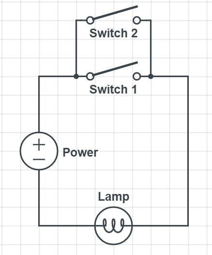
To better understand what makes a PLC so useful, here is a simple example. Say you have two switches and one lamp. When both switches are set to ON, you want the lamp to turn on. Simple enough, right? All you need to do is connect everything to the same wire, give it a power source, and you are good to go.

But what if you change your mind, and want to make it so that either switch can turn the lamp on? That is still pretty simple—all you need to do is wire Switch 1 and Switch 2 in parallel so that the current can go through either switch.
Problem solved. But what if on Monday through Wednesday you want to use the first circuit, and on Thursday through Sunday you want to use the second circuit? Now we run into some problems. Each design can only handle one scenario, meaning an engineer would have to redo the wiring twice a week. Not only would that be a waste of the engineer's time, but, nobody else would be able to use it while the system is being rewired. For a large factory, system downtime can translate to thousands of dollars lost per minute.
A possible solution would be to add a third switch which lets us toggle between the first and second programs, however that would make the wiring much more complicated and would require more expensive circuit elements to perform the logic. This might not seem like a big issue, but in real-world applications there are systems are much larger and more complicated than the previous example given. As a relay system grows in complexity, making changes to it can become exponentially more difficult and expensive. Even a basic change in behavior might require both thousands of physical changes to the wiring as well as countless hours of planning.
Imagine spending months designing a complex system like the one shown below, only to find out that the wires need to be to re-arranged.
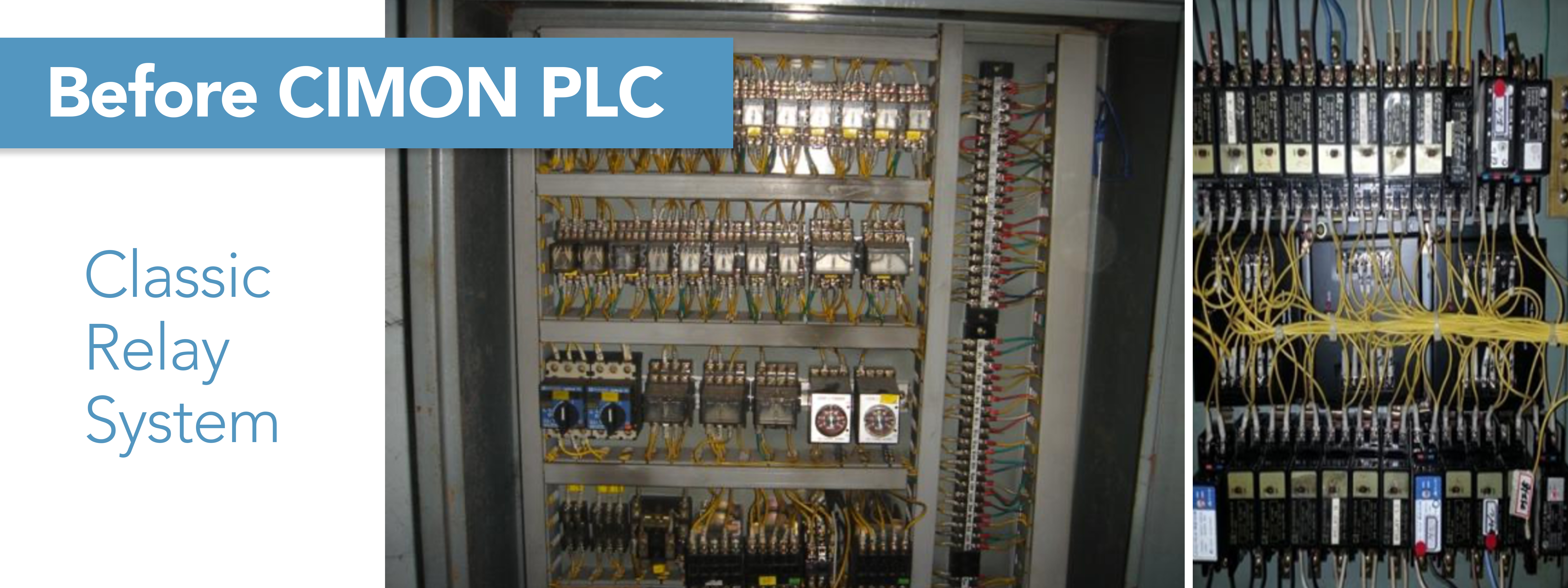
For decades, engineers were stuck with a difficult decision - either make a simple system that needs to be rewired for unique situations or make a complex system that can handle every situation. Neither solution is ideal, and each option comes with its own set of challenges.
What a PLC Does
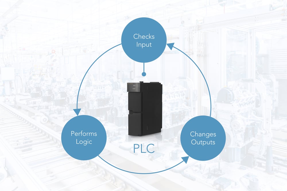
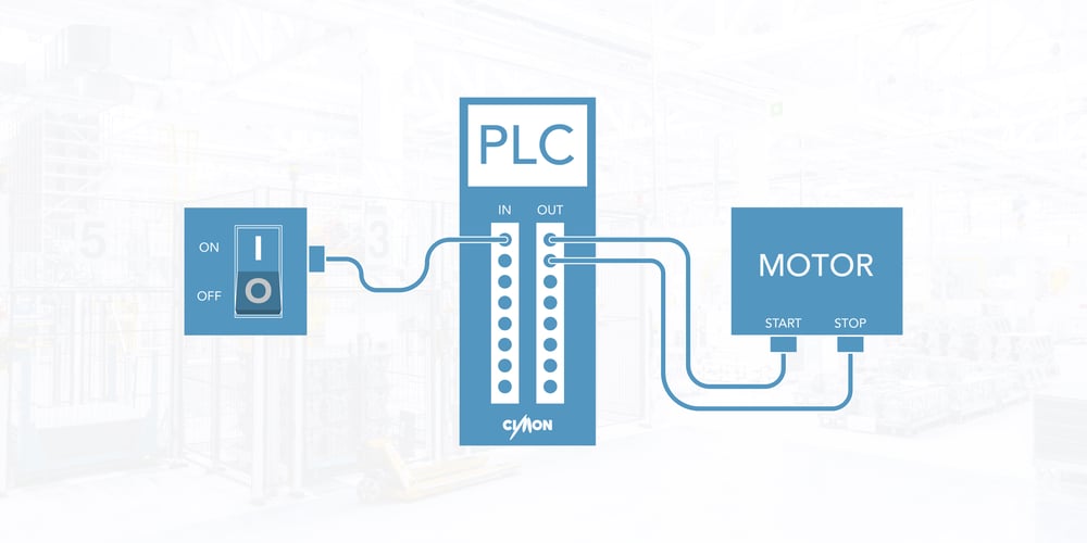
Enter PLCs. Instead of designing and then building the circuit ourselves, we just need to plug all of the inputs and outputs into a single PLC.
The PLC will read the inputs, perform any logic we tell it to, then turn the outputs on and off accordingly. For the example above, we can simply store both scenarios in the PLC program, then switch between them depending on the day of the week. With a PLC, this would happen automatically, with no downtime or human intervention required. Even if we later decided to change the program behavior, we would just need to edit the program and use only a few minutes of downtime to update the PLC. No need to buy new circuit elements or hire an electrical engineer.
A PLC also has its own internal memory for storing and manipulating data. This allows complex logic to be performed without the need for intricate circuitry. Internal memory also means we can store the values of inputs, outputs, and other calculated quantities, then analyze the data whenever we want to. This provides a simple way for companies to monitor device performance over time.
Ladder Logic
So how does a PLC actually work? Even before PLCs existed, engineers needed a consistent way to describe circuit behavior without thinking about the actual wiring. The main tool used to do this is called ladder logic. Here is the first switch/lamp circuit shown above, but now in ladder logic form:
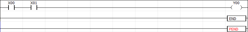
In ladder logic, the left-most side of the page is always powered on. Power flows from left to right, checking each element – or instruction – as it goes. In this example, our first instruction is an input – or contact – which reads the value of X00. X00 is just the name of an input bit, meaning it can either be ON or OFF. When X00 is set to ON, the right side of the contact is also turned ON, allowing power to continue moving to the right. When the power hits the X01 contact, it checks whether X01 is ON or OFF, then relays the result to the right. The result is that when both X00 and X01 are ON, power is able to flow all the way to the output – or coil – labelled Y00, turning the lamp on. If either X00 or X01 are OFF, then the power will be cut off at the corresponding contact, and Y00 (the lamp) will not receive power. The “END” and “PEND” symbols signify the end of the program.
A PLC will read through the entire ladder logic program, first from left to right, then from top to bottom. Once it reaches the end of the program, it will go back to the beginning and run again. This typically only takes a few milliseconds, meaning the program will run hundreds of times per second. In practice, a PLC is meant to stay on all the time, constantly updating its inputs and outputs. This speed and consistency is very important for industrial settings, where a small error can mean expensive or disastrous results.
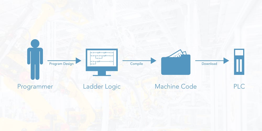
Most ladder logic is far more intricate than this and involves different kinds of instructions. Regardless, a program written in ladder logic will be much easier to understand and edit than a circuit diagram. Because of its usefulness for describing relay systems, ladder logic became the language of choice for programming PLCs. Engineers would draw a ladder logic diagram on paper, then convert it into a written set of variables and instructions, the language for which is called Instruction List. The instructions would then be entered into the PLC using a keypad. These days, a computer program lets you edit ladder logic visually, which a compiler then converts into machine code. A few other languages (Sequential Function Charts, Function Block Diagrams, and Structured Text) have also gained popularity, but ladder logic remains the industry standard.
Inputs and Outputs
So now you have a PLC, a working ladder logic program, and a collection of devices that you want to control. Now you just need to connect everything together. The traditional way to do this is to simply connect all of the inputs and outputs together, each using a separate physical wire. When a wire is powered on or off, the corresponding input or output (I/O) is also turned on or off.
This setup works fine if each I/O is a single bit, but if a device wants to communicate a number (for example, the speed of a motor or the value of a pressure sensor), then we need a way to encode the extra information. There are a few different ways to do this.
A common solution is to just use a variable Voltage (or Amperage) to represent a variable data value (also called an analog value). For example, a current ranging between 4 and 20 milliamps can be used to represent a temperature between, say, 0 and 100 degrees Celsius. Then, a current of 12 milliamps would represent a temperature of 50 degrees Celsius. Another option is to use an alternating current, where a higher frequency represents a greater number, and vice-versa. Some PLCs allow you to connect variable-current wires directly to the input/output terminal, but because different devices encode analog values differently, most PLCs require an expansion unit to do this.
Bits, Bytes, and Words
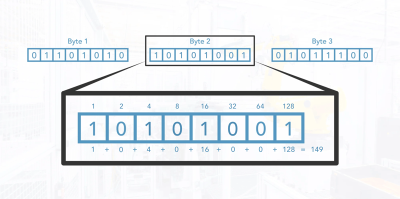
Regardless of how an analog value is transmitted, we still need a way to represent numbers other than 0 or 1 inside of the PLC. Otherwise, we would not be able to perform mathematical operations. Although a processor technically treats everything as 0’s and 1’s, we can group multiple bits together to represent larger numbers. For PLCs, the standard is to use 16 bits (called a WORD) or 32 bits (called a double word or DWORD). Other common groupings include 8 bits (a byte) and 4 bits (a nibble), though the names for each group can change depending on the type of processor. In a WORD, each bit represents a power of 2, which is either added to or not added to the total depending on whether the bit is on or off. For example, the first bit being on would represent a value of 1, the second bit a 2, the third bit a 4, and so on. This is called binary or base 2 representation, and is an important concept not only for PLCs, but for computer science in general. This is contrasted with base 10 representation, which is how people typically write numbers. The picture below shows an 8-bit binary number and how it converts to a base 10 value.
Because there are different ways to represent numbers in binary (for example, you might want to use negative numbers or fractions), different WORDs need to be treated differently. Fortunately, each device only cares about the actual set of bits that it sends out and the bits that it receives back. It is up to the programmer or engineer to keep track of what each WORD actually means, and how it should be handled within the PLC program.
Communication Standards
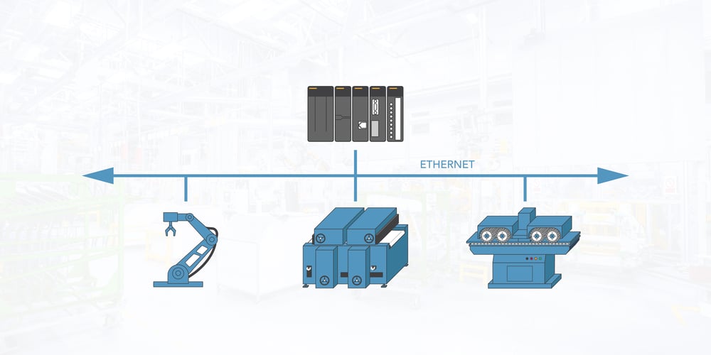
Modern PLCs can also receive and send data using serial or Ethernet cables. This means that instead of attaching separate wires for each bit or analog value, each device just needs a single cable to connect to a network. This allows a connected PLC to access any other device on the network. One drawback is that this can result in lots of data flowing over the same cables at the same time. More importantly, not all manufacturers encode data the same way. If you want two different device types to talk to each other, you may need to decode and then re-encode each packet of data.
To avoid this issue, there are various communication protocols for sending and receiving data. Each one has advantages and disadvantages, and not all devices support all protocols. Perhaps the most well-established and widely supported protocol is called Modbus, which works with both serial cables and Ethernet networks. If there is no direct protocol for interfacing two devices, then usually Modbus can be used to bridge the gap. There are also newer and faster protocols, including EtherCAT – which allows for high-speed transfer over Ethernet cables – and Open Platform Communications Unified Architecture (OPC UA) – which allows devices to communicate over an internet connection. Some devices are even able to connect wirelessly using a WiFi network, but wired connections are often preferred because of their speed and reliability. All of these standards allow a PLC to communicate with many different kinds of devices, regardless of the manufacturer.
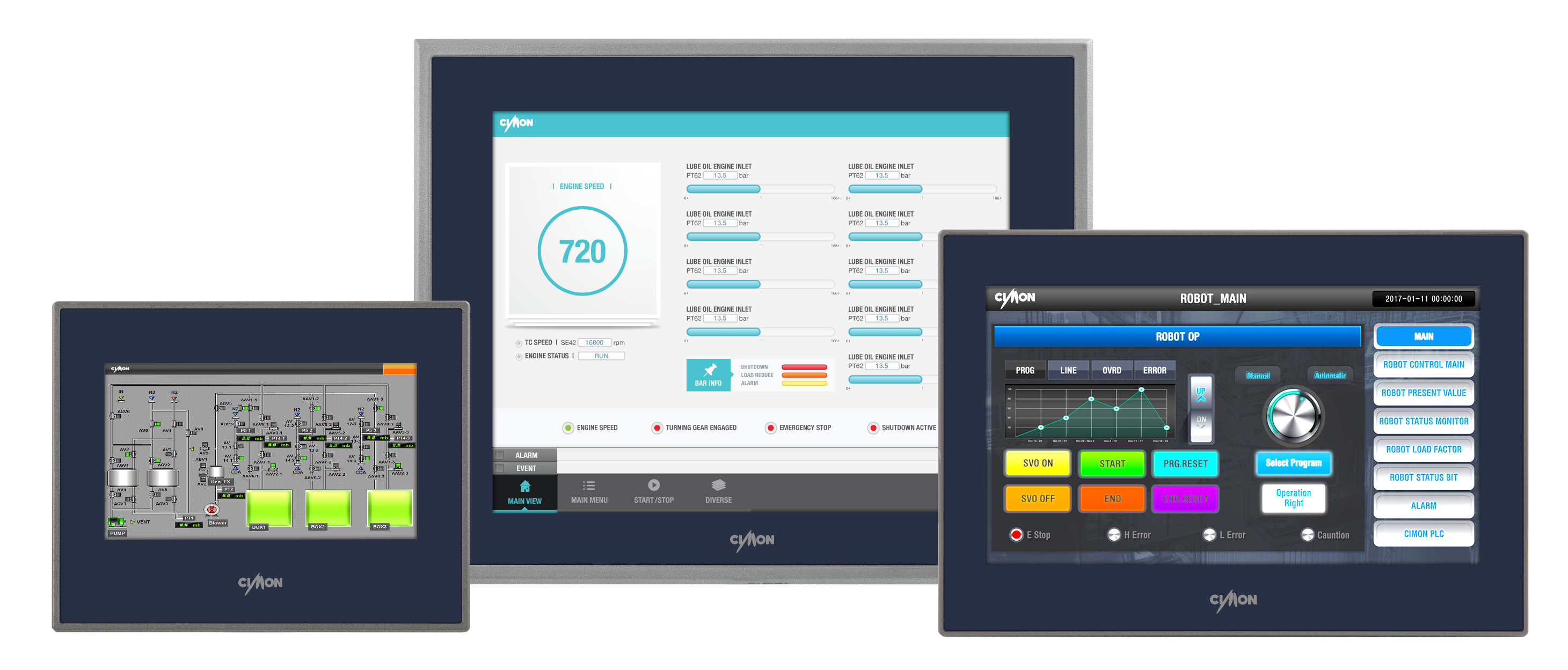
Hopefully, you now have a reasonable idea of what PLCs are, how they work, and why they are useful. To summarize, a PLC takes input data from other devices, processes it, then sends output data. PLCs can be used for a variety of applications.
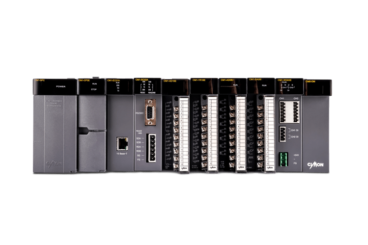
If you would like to learn more about PLCs and ladder logic, you can visit the CIMON website and create a free account to download CICON, our free PLC-editing program. CICON lets you create and edit ladder logic programs on your PC, and even provides a simulator tool for running programs without a PLC. CIMON also offers other automation products, as well as online training and technical support at no additional cost.